i finally got around to it, mofos. here is the latest installment of alex’s helpful series on how to build your custom metric chopper or bobber frame:
Picking up where we left off with two concepts to start; confidence and common sense. “What’s he babbling about confidence for,” I hear everyone ask. It’s simple, as in most things, if you feel apprehensive about doing this then practice, practice, and practice with cheap steel tubing like water/plumbing pipe or whatever until you feel happy to get to work properly. That’s common sense. Remember that you will be riding this creation and you don’t want it failing on you. Also, which is arguably worse, you will probably at some time in the future sell it, thereby putting the results of your skills into someone else’s hands. If your confidence is lacking and you’re feeling apprehensive, build your first frame following this series of articles out of some cheapo water pipe. It won’t be wasted. At worst you can flat black paint it with a rattle can and ask your local bar to hang it off the ceiling. As with our power tools tip, build up your confidence with this stuff and feel happy you can tackle the job before you start.

You should now be looking at a pretty accurate mock up of the frame design you dreamed up on your napkin/CAD package/drawing board. My suggestion at this stage is this: You played with your sketches and drawings for a long time to get your ideal look and style, so don’t rush it now. Take some time outs to look long and hard at your mock-up and don’t even glance across at your steel and parts collection until you’re 100% happy with what you’re looking at in your jig.
Your first bends should be the downtube bends that send the lower rails up to the steering neck. Measure the angle on your mock-up carefully and double check it with the one you wrote down earlier. If they’re different, no worries, we’ll tweak it soon. We are making two of these, so measure carefully the length of tube required. We have to go from the neck curve down past the engine and back to the rear spindle carrier. Measure this length and chop off two lengths about six inches longer than the measurement. With this type of frame that we are building, we can make the distance between the rails (from the forward bends backwards) the same all the way back because we are using no bigger than a 130mm tire. Things can get complicated when the lower frame rails have to be bent in two directions (up and out) at the point where they kick up to meet the rear spindle carrier if we are using wide (generally wider than 150mm) rear tires. Many builders end the lower rails just past the seat post and use two hoops as the upper and lower rear rails. Thankfully, as this is a somewhat debatable practice, we needn’t be getting into it with this article, although we may in the future.
Having completed the mock-up and before we put a piece of tube into our bender, we need to make a little tool as a guide. Chop off about 18 inches of the tube you are using and create a line around it’s circumference with a permanent marker, being sure you can see it clearly. Place this piece in your bender with the line at the bender’s start point and bend it through the number of degrees you need those bottom bends to be. Now, look carefully at the other end and make a line around where the bend ends. This is not the easiest thing to judge, and the best way to do so is subjective. One must simply be able to tell. Look at it and get the feel for it, and make your mark. This is now our homemade gauge to judge where to start our bends. Bare with me all and will become clear as we progress.
You can take the engine out of the jig now and being careful not to disturb any of your mocked-up pieces of tube, take the bend mock-up you just created and lay it carefully against the downtube where the bend should start and tape it in position so it follows the downtube and the lower rail perfectly. Now measure the distance from the top line on the bend template to the neck, add two inches, and that’s the position of the first bends on the downtubes. Mark these tubes in the same way as our template with a permanent marker and bend them identically. You can now take the broomstick out of the jig and replace it with both of these tubes. Just for the moment lean the tops of the downtubes against each side of the neck, as we are going to wander off on a slight tangent for a minute or two.
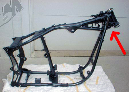
Depending on how detailed you’re drawing or sketch was, you may or may not have gone into great detail on how the downtubes and backbone meet up with the neck although it is very important. There are various ways of doing this. Some are good some are not so good and some are downright scary. What we need to achieve is to have as much weld area as possible. Look how Harley achieves this in this pic:
 The down tubes meet the backbone and only the backbone tube is directly attached to the neck. Below the backbone is a plate structure that boxes it all in and makes for a very solid and secure joining of all the components. It’s a very efficient way of putting it all together, although the downside is if the neck area is in plain view and not hidden below a tank, it can make the frame look very bulky at the front end. It’s good with a lot of weld area on the neck, but we won’t be doing that on this frame.
Another popular method is to make all the tubes meet the neck. This is okay but it can be a bit risky as the amount of weld area achieved this way isn’t very much and we have a few hundred pounds of bike and rider hanging off it.
Let’s not do that. We can do a lot better with very little effort.
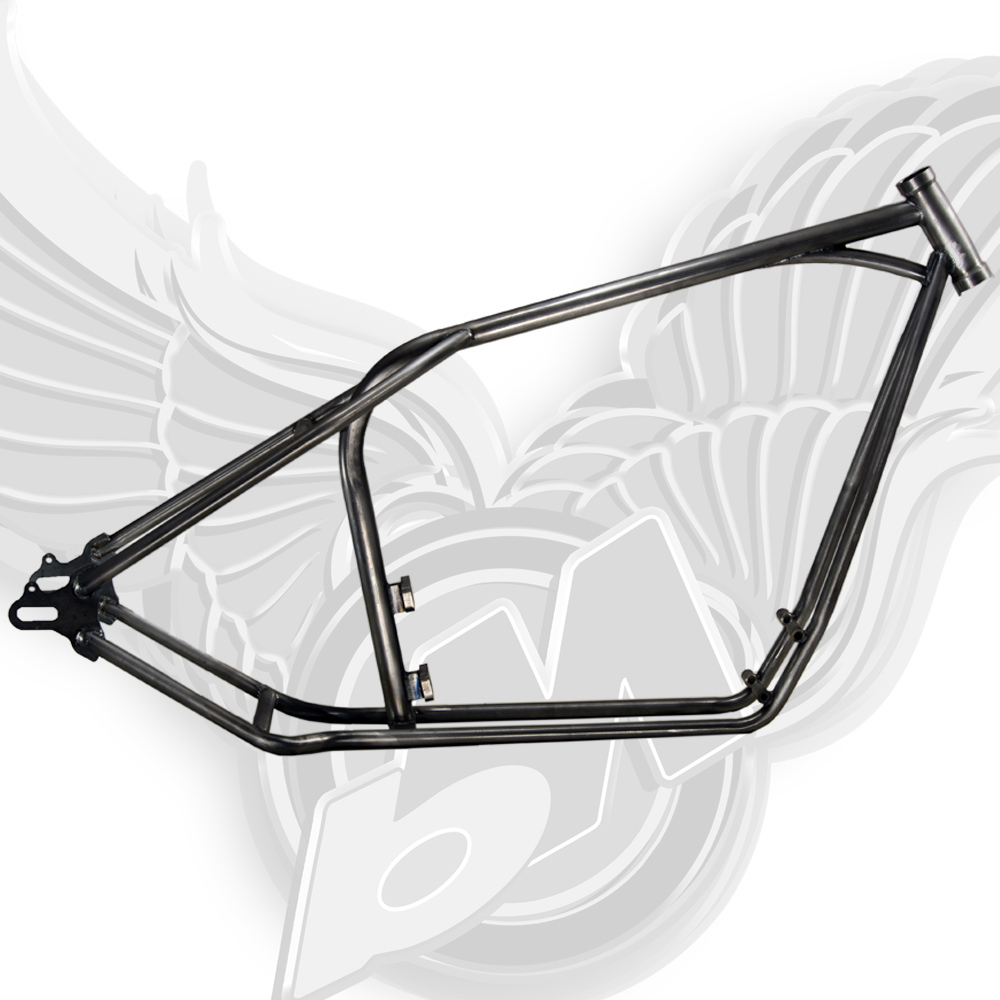
A third way is to join all the tubes at the neck as above, but with some gusseting. As you can see from the images below, this not only is a very neat and tidy join and it maximizes the weld area that is available. Not only are all the tubes welded to the neck all the way around their circumferences, but the gussets on each side of the tubes are 1/8″ plate which is pretty much the same thickness as the tube wall. This is important because the weld will be stronger if the two pieces being joined are the same thickness. It’s a pretty safe bet this particular neck isn’t going anywhere under any conditions on the road. We’ll be doing something similar.
Now we have our downtubes sitting on the jig, leaning against the neck. Make sure they are touching the neck towards the bottom, ideally about a quarter inch or so above the bottom of the neck at their lowest/most forward point.
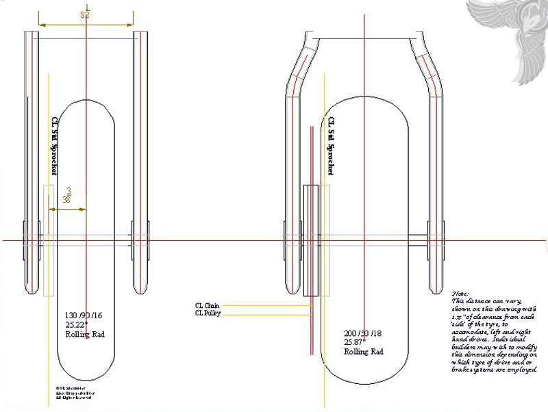
The next thing to do is to nail down the distance between the lower frame rails. This is determined by a number of ways. In an attempt to keep it simple, we can distance our frame rails at 8.5″ between the rails, or 9.5″ on centers. This distance is needed to clear a 530 chain on a 130 wheel tire. The sketch below paints a thousand words. The most critical measurement is where the centerline of the sprocket lies. In this instance we are leaving ¼” ish for the chain-to-tire clearance.
Looking at that sketch it’s easy to see how to get to the dimensions we need to get our lower frame rails right. I’ve put a 200mm tire example in it to illustrate the procedure a little better. The trick is to accurately measure the width of the tire you’re actually going to be using (my Metzler 200 is actually closer to 190). This is crucial to getting the wheels in line with each other in the frame. As far as the front is concerned, as long as the neck is firmly in the jig and the forks aren’t bent, it looks after itself centreline wise.
The rear is a different ball game and it’s very easy to get it wrong. We need to know what size our chain is and how far away from the outside edge of the tire the sprocket is. Remember this procedure when you’re using a donor wheel and the sprocket is already fitted to it. Give yourself a quarter of an inch clearance between the edge of the tire and the and certainly not less that 1/8″. Space the sprocket out with washers if need be. A “standard” flat washer is generally 1/16″ thick and don’t forget how worn chains move sideways as well. In the example above, the sprocket center is 3 and ⅜” off center and a 530 chain is one inch across, give or take a thousandth of an inch or two. To be honest, if you work with that chain measurement for everything, as a rule when using a smaller sized chain you will know you have enough clearance.
As we can see from the sketch with a 130 tire, the center of the sprocket is 3 and ⅜” from the center line, given that the chain is 1″ wide and the outside of the chain is 3 and ⅞” from the center line. This makes the inside of the chain 2 and ⅞”, double this distance and we end up with a usable width of 5 and ¾” and if our 130 tire is 5 and ¼” across, we have the necessary ¼” of clearance between the chain and tire. If we clamp our rails in the jig at 9.5″ on center (8.5″ between them), we have ¼” clearance between the tire and the chain and ⅜” clearance between the frame and the chain. It’s always better to start as close to the tire as you can get with the option of coming out ⅛” or so if needed to help with the engine sprocket line up.
Lean the frame rails on the steering neck and mark up the front/top of the front rails for coping onto the neck. We have to do this before we bend the lower rails up to meet the rear spindle carrier. Until the front downtubes are coped and tacked in place on the neck, we are unable to determine the top of the lower rails, which we need before we can bend them up to the rear spindle. Having clamped the rails into place, cut two lengths of tube with each end notched to fit between the lower frame rails. Again, it’s very important they’re cut the same length but don’t tack them on yet, as we will be using them later. For the moment they will act as distance pieces to keep the lower rails straight and parallel to each other. This is best done with a 1″ hole saw in the pillar drill and is easy enough to work out. We need them to be 8.5″ between the inside of the cope. See the sketch below:
The center marks on the sketch are where you “center pop” and drill through with your 1″ hole saw. Mark a line along the length of tube at the center to ensure that both your cuts at each end will be on the same plain. Clamp each in your drill press and drill ’em through. Voila! Now place these in between the lower rails to keep them parallel and straight to each other, and clamp the assembly down.
I can see even the front row falling asleep on me at this point, so we’ll break here and continue in the next installment, should Trent get it up in a timely manner. Get the coffee brewing and I’ll try and pop ’round to mark your efforts…

Get the best of bikerMetric directly in your inbox, once a week, every week.
[wysija_form id="1"]
 bikerMetric custom metric bobbers, choppers, and cafe racers by honda, yamaha, kawaski, and suzuki


Nice info, thx.